Suitability for pick-and-place bottom camera

Hello, I’m wondering if I could use an H7 with global shutter module as a smart ‘bottom camera’ for a PCB component pick-and-place machine. The goal is to look at an SMD part held by the nozzle and check whether the rotation or position needs alignment. Ideally this would have “fly-by” capability where the nozzle does not stop over the camera.

The overall procedure would go like:

  1. Receive package type (eg. 0805, SOT23 etc) to be identified, over UART probably
  2. Wait for external trigger
  3. Grab frame buffer and process, probably 320x160 mono
  4. Output xy offset and rotation over SPI

So far I can’t see any obvious roadblocks to achieving this, let me know if I’m wrong about that. I’m also wondering what kind of time I might expect the processing to take, because if the nozzle gets to the destination first and has to sit around waiting, the advantage of the fly-by is kinda lost. The trigger latency also needs to be highly consistent.

Hi, the triggering can be done precisely. As for the frame rate. You can achieve 40 FPS usually in triggered mode. So, you’d need to keep your algorithm down to 25ms. Depending on what you are doing this is possible.

Thanks for the reply. My board and global shutter module arrived today.
Since I have some STM32 and image processing experience, and the driver code for grabbing a frame is available in your github, I might have a go at making my own custom recognition algorithm. But there is a pretty good chance I will fall on my face and give up. In that case, there is no reason I couldn’t restore the original bootloader+firmware right?

Yeah, just connect BOOT0 to 3.3V and you can reset the firmware.

Just an update on this… as expected I fell on my face pretty quick when trying to set up my own firmware, couldn’t get any response when doing I2C scan. Then I tried using the camera as it was intended, with micropython and the IDE etc. Should have done that to begin with because things became so much easier - for some reason I had it in my head that python = slow, which is apparently not the case.

Anyway, I have been experimenting with capturing a 128x160 frame with the global shutter module and with this tiny framebuffer it can snapshot and find blobs in about 20ms or a little less, so could almost handle around 50fps. The trigger timing is about as perfect as I could need. Also very helpful is the large RAM which allows me to snapshot multiple images in quick succession in a very time-sensitive phase first, and defer blob-finding until afterward.

To check all this I set up a test rig which swings four pretending nozzles over the camera. Each snapshot and framebuffer copy seems to take about 8ms, then I need to sleep for 24ms until the next ‘nozzle’ arrives. This means snapshots could actually be taken even quicker, but I started to get some motion blur with faster movement and it’s already plenty fast enough. After all the photos are taken, blobs are found and reported over UART about 40-50ms after the last snapshot. The UART also reads in instructions about what type of processing to do.

So it’s basically everything I hoped for. Probably the only thing extra I’d want is a few more GPIO pins. For those interested in a demo, you can see this video: https://www.youtube.com/watch?v=mpmJ5q4aA90

Great! I posted your video on Twitter and will share with our email list on the next update!

Yeah, regarding Python being slow. The firmware is in C and a lot of stuff is SIMD accelerated. So, Python is really just the thin management layer in the top.

You can go faster if you keep the exposure time really small. To do this you must change the illumination setup.

Doing some more work on this, with just a single position capture and working with only the main frame buffer instead of copying to different buffers, and viewing the result in the IDE instead of on a LCD screen, I came across some oddities.

The first is that triggered mode seems to cause the image shown in the IDE to be old, that is, each time I trigger the snapshot the IDE shows the result from last time. This can be worked around using print(img.compressed_for_ide()) after processing.

I also found that calling to_rgb565() after all the capture and blob-finding is done, appears to somehow affect the trigger timing. Here is a minimal case:

import sensor, image, time
from pyb import ExtInt, Pin

sensor.reset()
sensor.set_pixformat(sensor.GRAYSCALE)
sensor.set_framesize(sensor.QVGA)
sensor.skip_frames(time = 1000)

sensor.ioctl(sensor.IOCTL_SET_TRIGGERED_MODE, True)
sensor.set_auto_exposure(False, 400)

cap = 0

def callback (line):
    global cap
    cap = 1

ext = ExtInt(Pin('P7'), ExtInt.IRQ_RISING, Pin.PULL_DOWN, callback)

light = Pin('P9', Pin.OUT_PP)
light.low()

while(True):

    if (cap == 1):

        light.high()
        sensor.snapshot()
        img = sensor.snapshot()
        light.low()

        # find blobs here, usually

        img.to_rgb565() # <--- affects capture timing?!?

        print(img.compressed_for_ide())

        cap = 0

Here is the result when to_rgb565() is called:
with_to_rgb565

Here is the result when to_rgb565() is not called (this is about 15ms earlier, the blobs are moving from right to left):
without_to_rgb565

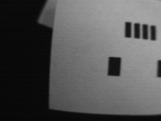
I find this strange because to_rgb565() is called after the snapshot is completed. How can it cause the framebuffer content to be from a later time? Finding blobs results in the blobs matching up correctly with the displayed framebuffer in both cases. Overall it’s behaving like the to_rgb565() causes a slight delay before the capture.

I don’t think the print(img.compressed_for_ide()) is causing this, I get the same result without it (except for on each trigger the IDE shows the capture from last time). I also tried copying to another buffer at the time of snapshotting, but this gave the same outcome:

img = image.Image(320,240,sensor.GRAYSCALE) # before main loop
...
sensor.snapshot().copy(copy_to_fb=img)
...
img = img.copy(copy_to_fb=True)
img.to_rgb565()

btw the reason there are two calls to sensor.snapshot is because with only one, the low exposure time results in very inconsistent and grainy results, for example:
without_doubleSnapshot
without_doubleSnapshot2
without_doubleSnapshot3

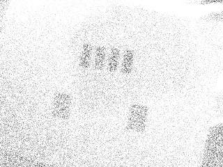
In my early experiments this was a very disappointing discovery, until just by chance I happened to trigger two captures in quick succession, and noticed the result was nice and clean. Seems like the first exposure blows the cobwebs off the ADCs in the sensor somehow. In any case, doing just a single snapshot instead of two does not change the weirdness with to_rgb565().

While I’m here, you may have noticed in my video that the first trigger after startup is always off by quite a lot, just wondering if there’s any reason for that. The second and subsequent triggers are perfectly timed.

These are not show-stoppers by any means, just a few things I found weird.

I’d recommend to snapshot first before the actual capture as you need to startup all the DMA logic which will be asleep until the first snapshot. After that it should be alive to receive the image.

As for to_rgb565(). When converting a grayscale image to an rgb565 image this can’t be done in place. So, it’s allocating a second image, and then duplicating pixels and whatnot. I wouldn’t call it a free method.

If you want to control what’s in the frame buffer I suggest you turn off automatic updates using the omv module and then send images using compressed_for_ide(). This ensures you are looking at the most recent image and not the last image. snapshot normally works by sending the last image to the IDE (or drops sending it if the previous one has not yet been sent).

BTW, compressed for IDE blocks and effects timing as it kinda forces data to be sent to the IDE and doesn’t transfer it async.

Thanks, this is great. Doing one snapshot before launching into the main loop makes the timing correct on the first trigger, so I don’t need to keep pressing my button twice after every edit. And using omv.disable_fb(True) allows me to keep the bytes intended for the LCD (swizzled red/blue) out of the IDE view. Now one press of my trigger results in just that capture showing on both IDE and LCD with no flicker in between, perfect!

Yeah it’s ok that the IDE display is slow, it’s just preferable while developing so I don’t need to put my old-man glasses on to see the tiny LCD screen. Also, I’ve moved to 320x240 for the processing, which the LCD can’t really show fully.

btw to match SMD part rotation and offset with a known footprint, I’m trying an idea I had where the convex hull of the blob points is used as a descriptor of sorts. More specifically, the longest side of the hull for most parts should usually be sufficient as an orientation. My assumption is that parts should not be more than 45 degrees away from the expected orientation, otherwise there are bigger problems to solve.


chull

I like that this allows for discarding unimportant points quickly, especially for the likes of QFP48 etc. I think it will also be reasonably forgiving with clusters of many smaller blobs where neighbors might get blurred together. Depending on the package, some blobs could even be completely missed and it wouldn’t matter.

Another nice thing is that a large number of patterns could be generated with minimal human effort, by exporting their solder pad layouts (eg. I use DXF export from EasyEDA) and making a tool to generate the pattern hulls. The copper footprints are not exactly the same as the legs on the components that the camera will see, but should be close enough for the purpose of finding a rotation and offset.

Anyway, I don’t know how this kind of matching is done normally, so perhaps I just described a common method that everybody already knows about. Just wondering if you’ve come across any clever tricks in your adventures with image recognition…

Typically it’s an L2 norm. E.g. reduce the number of points to just the required amount. I.e. if two points are near each other and the line passing through them doesn’t have much of an angle you can optimize them out and make them one point.

After that, you find the centroid of the points, then sort them by angle around the centroid. You might actually want to do this first as it makes it really easy then to do the above step.

Finally, then the list of points should have a known length… which should match templates of the same length, so, you can then just find the distance metric of templates with the same length. However, the points may be rotated so there order may not match the template. So, you need a way to shift the points to handle that. Note, you’d do the distance metric from the center of the points centroid.