Hi,
I bough an Nicla Vision board and flashed the board using openMV. Now the RED LED is continuously on, and switches off after 14 seconds and then the LED is on again.
Double tapping the reset button doesn’t help nor the device is enumerated on the USB port. My USB cable is good.
Please advice how to proceed.
Best regards
Carl.
Hi, I pushed our an update to the IDE this morning with an updated release that fixes the way the erase-flash-disk option works. This fixes the issue. However, if you clicked the erase flash disk button before today then the board is bricked.
Arduino’s default bootloader is larger than 128K and when the erase option is clicked on loading the board we erase the second 128k page on the system… for the Arduino Portenta this is what is expected needs to be done… but, for the Arduino Nicla the bootloader has some code in that extra 128K. This bricks the bootloader and the board. We were not informed this was not the correct behavior until this morning.
Without a jtagger this can’t be fixed as you need to reflash the board bootloader. If you have a jtagger I can provide help on how to do that. Please contact Arduino otherwise for a replacement.
There’s also a way to use the default STM32 bootloader to reload without a jtagger. The BOOT0 pin needs to be exposed. If it is then the IDE can reflash the our firmware and Arduino’s bootloader.
I can check on that in a bit.
Hi,
Thanks for prompt responding. We have a couple of jtag programmers here.
Please give me some pointers which image to use and (if applicable) some flash memory base adresses where to flash it, or are the adresses already defined in the image?
Br
Carl
use the default STM32 bootloader
The ROM DFU bootloader doesn’t work on USB-HS.
Please give me some pointers which image to use and (if applicable) some flash memory base adresses where to flash it, or are the adresses already defined in the image?
I’d just upload the latest Arduino bootloader to 0x0 and use it to upload our firmware or Arduino sketches. The updated bootloader also fixes this issue by limiting the bootloader size to 1 sector. I think you can find it in mbed core, bootloader version should be 23
Hi,
I am quite a newbie on arduino/openMV etc. Do you have some url’s where to find the bootloader and images?
Br
Carl.
I’ll ask and get back to you.
I have the same problem as you. The 14s red blink of death.
Even with an ST-link plugged on the SWD/JJTAG pins, I am not able to see the device.
I’ve tried to upload a STMCube blinky and an Arduino 2.0 blinky (both were working fine).
I’ve tried to select in the Arduino IDE 2.0 tools->programmer: “st-link” then burn bootloader but it didn’t work.
Even with an ST-link plugged on the SWD/JJTAG pins, I am not able to see the device.
I’d double check the connections, it should be recoverable with SWD. You should connect SWD, SCK, GND, and NRST too.
I’ve tried to upload a STMCube blinky and an Arduino 2.0 blinky (both were working fine).
Nothing will work because the bootloader needs to be fixed first.
Hi,
could somebody supply where to connect the JTAG to?
The datasheet https://docs.arduino.cc/static/b577f757d6ec2d81e820a3d29b08d3b9/ABX00051-datasheet.pdf specifies “J3 Fins” which are according to the datasheet 8 pins of which some are the JTAG required pins. But the PCBA itself has the J3 header which is strangely enough a 5 pins header, I expected it to be 8 pins.
Also a BOOT0 pin seems tot to be exposed.
So i’m puzzled here…
[Edited]: I found it here: https://docs.arduino.cc/learn/hardware/nicla-form-factor#fins-1
Does somebody has a picture how to apply the mentioned header?
Br
Carl.
Hey, here’s the bootloader binary, this is the updated one:
@iabdalkader I’ll relook this morning but I’ve only uploaded my code via Swd/Jtag so far and the connection didn’t change between the normal and broken state. I’ll let you know.
[edit] The pinout is good with the st link.
Also thanks for the bootloader, will try once I’m at the office.
@Wolfc01 on the bottom side of the nicla, you’ll see tiny fins between the through holes. They are there.
[edit] Here’s the picture
I don’t have a board to test with, but I think you need to provide VDD I/O to stlink that’s the (VAPP/Target VCC on pins 1, 2) note the board’s I/Os are 1.8v.
The pins :
P7 : 1.8V
P6 : SWO
P5 : NRST
P4 : SCK
P3 : SWD
6 : GND
are connected to st-link. Like I said earlier, It was working before and I didn’t change the wiring.
Hi,
I soldered some pins to the fin’s, and I used SWD (Serial Wire Debug), and STM32QubeProgrammer. I starten openMV, and it remindedme to update some images. Then I flashed, and everything works now.
Thanks for help…
Br
Carl.
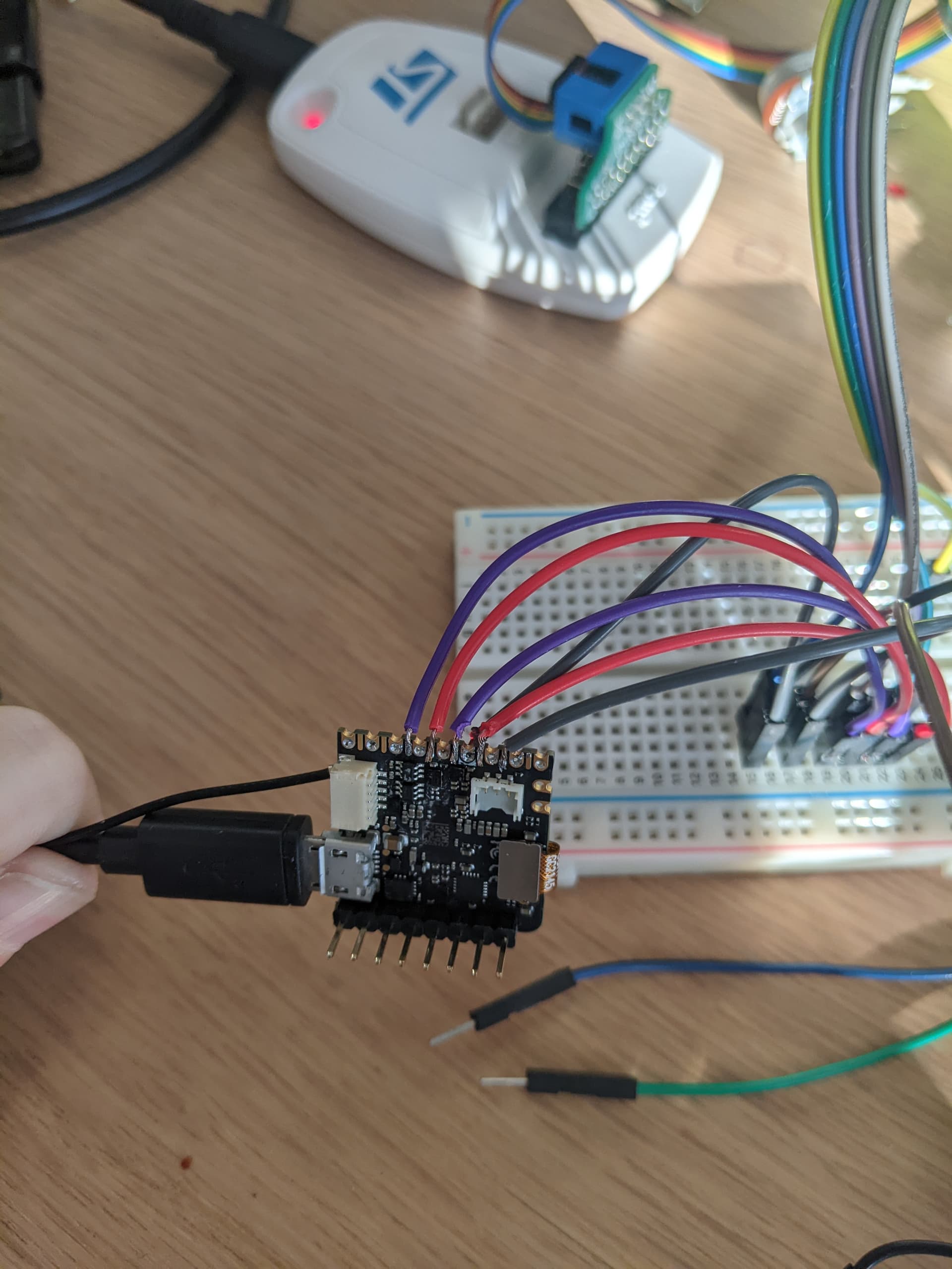
@Wolfc01 Can you please share the pin connections between the board and stlink and any photos,commands, tools and steps you used to fix this, for others who need it ? Thanks.
Here you go: instructions how my collegue got the NICLA VISION board working, after I bricked it:
First I soldered a 2.54mm pitch header to pins P3 to P6(you can also use wires or an edge connector). Then I connected these Pins to the corresponding pins from a ST-link(I used the ST-link from a nucleo board, with the CN2 connectors disconnected). Then install STM32Cubeprogrammer, and use it to download the following file: (https://github.com/arduino/ArduinoCore-mbed/raw/master/bootloaders/NICLA_VISION/bootloader.bin).
To upload the file to the Nicla vision board, provide power to it(I used the USB connector). When it’s powered the red led was continuously on (because it was bricked).
Now connect the ST-link to your computer and start the stm32Cubeprogrammer software and click on connect. It should be connecting to the stmH7 on the nicla vision. When connected, click on the + icon and select openfile. Then select the ‘bootloader.bin’ file and download it to the nicla vision with the download button to the right. When the download is completed the red light should go off and the nicla vision board should work again.

Br
Carl.
1 Like