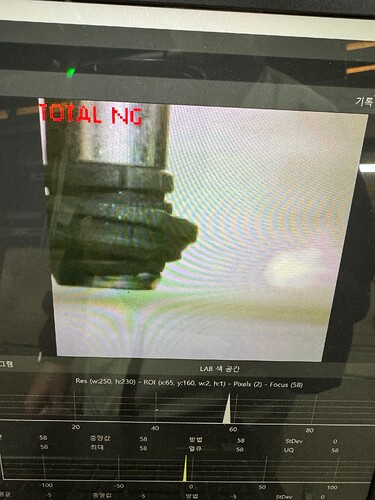
Hello, we are currently applying 4x zoom lenses to open mv h7puls and rt1062 to detect errors after assembling products to facilities in the factory, and we are setting the camera quality to qvga when detecting errors through color.
This is because all the screens of the camera do not appear on the LCD screen attached to the back.
If you connect the PC to the camera and look at the screen, qqvga / qvga / vga all show well without being cut off.
However, if you apply the code to main.py and look at the screen through the rear lcd attached to the camera, all the quality other than qqvga will be cut off.
Can this be compatible? I’ll attach my code and photo below.
-code-
import sensor, image, time, pyb, lcd
thresholds1 = [(60, 100, -10, 10, -10, 10)]
thresholds2 = [(20, 40, -10, 10, -10, 10)]
sensor.reset()
sensor.set_pixformat(sensor.RGB565)
sensor.set_framesize(sensor.QVGA)
sensor.set_windowing((70,10,300,300))
sensor.skip_frames(time = 500)
sensor.set_auto_gain(False)
sensor.set_auto_whitebal(False)
led_R = pyb.LED(1)
led_G = pyb.LED(2)
led_B = pyb.LED(3)
led_R.off()
led_G.off()
led_B.off()
lcd.init()
from pyb import Pin
pin1 = Pin(‘P1’, Pin.IN, Pin.PULL_DOWN) #차종1
pin4 = Pin(‘P4’, Pin.IN, Pin.PULL_DOWN) #차종2
pin5 = Pin(‘P5’, Pin.OUT, Pin.PULL_DOWN) #OK
pin6 = Pin(‘P6’, Pin.OUT, Pin.PULL_DOWN) #LCD 제어
pin9 = Pin(‘P9’, Pin.OUT, Pin.PULL_DOWN) #NG
Count_I = 0
first_ok = 0
first_ng = 0
second_ok = 0
second_ng = 0
pin6.value(1)
while(True):
img=sensor.snapshot()
lcd.display(img)
value1=1
value4=pin4.value()
if value1==1:
Count_I += 1
if Count_I <= 9:
blobs1 = img.find_blobs(thresholds1, roi=(9, 54, 75, 76), pixels_threshold=50, area_threshold=20, merge=True, margin=100) #부쉬
blobs2 = img.find_blobs(thresholds2, roi=(101, 55, 10, 86), pixels_threshold=50, area_threshold=20, merge=True, margin=100) #우측
blobs3 = img.find_blobs(thresholds2, roi=(12, 159, 73, 11), pixels_threshold=50, area_threshold=20, merge=True, margin=100) #하단
if blobs1 or blobs2 or blobs3: # 어느 하나의 영역에서라도 객체를 찾았을 경우
for blob in blobs1:
if blob.area() > 40 and blob.area() < 10000:
img.draw_rectangle(blob.rect(), color=(255, 0, 0))
img.draw_cross(blob.cx(), blob.cy())
for blob in blobs2:
if blob.area() > 40 and blob.area() < 10000:
img.draw_rectangle(blob.rect(), color=(255, 0, 0))
img.draw_cross(blob.cx(), blob.cy())
for blob in blobs3:
if blob.area() > 40 and blob.area() < 10000:
img.draw_rectangle(blob.rect(), color=(255, 0, 0))
img.draw_cross(blob.cx(), blob.cy())
img.draw_string(0, 0, “NG”, color=(255, 0, 0), scale=2, mono_space=False)
lcd.display(img)
first_ng += 1
else: # 세 영역 모두에서 객체를 찾지 못한 경우
img.draw_string(0, 0, “OK”, color=(0, 255, 0), scale=2, mono_space=False)
lcd.display(img)
first_ok += 1
else:
if first_ok > first_ng:
led_G.on()
print(‘total OK’)
pin5.value(1)
img.draw_string(0,0,“TOTAL OK”,color=(0,255,0),scale=2,mono_space=False)
lcd.display(img)
else:
led_R.on()
print(‘total ng’)
pin9.value(1)
img.draw_string(0,0,“TOTAL NG”,color=(255,0,0),scale=2,mono_space=False)
lcd.display(img)
else:
img.draw_string(0,0," NO INPUT",color=(255,255,255),scale=2,mono_space=False)
print(‘no input’)
lcd.display(img)
pin5.value(0)
pin9.value(0)
Count_I = 0
first_ok = 0
first_ng = 0
second_ok = 0
second_ng = 0
led_R.off()
led_G.off()
led_B.off()
-picture-

