OpenMV H7 Plus with new fw is now seen as H7

Hi all,
I am new to OpnMV , I first started with OpenMV h7 and play with machine vision example :

  • haarcascade_face_detection is running but do not show any face detection on a grayscale frame , terminal show only fps WHAT IS THE REASON?
  • fomo_face_detection is running and show face detection with a circle on a color frame and terminal show position xy and score of face.

Looking into RomFs I saw that in model zoo there is a person detection model
I selected it and the RomFs window bar show all the files have a size of 419 kB over phisical size of 128kB and I can not commit( button is graied)

Reading on web I see that H7 has a limited RomFs to 128Kb
instead H7 Plus has 34MB .

So I purchassed an H7 Plus at first connection I upgraded the fw with last one
the result has been that now H7 Plus is


recognized by IDE as an H7 but with an OV5640 sensor,
the RomFs size is 128kB.
What is going on?
Thanks in advance for any help

Hi, you have a clone unit. We’ve never released an H7 Plus with a USB-C connector. The cloners installed the wrong firmware.

Anyway, attach pin between BOOT0 and RST, plug into the PC, click connect and select H7 Plus from the IDE, and then it will reflash it and put the right firmware onboard. Make sure to reset the ROMFS and erase the flash drive.

If you’re board doesn’t work after this… not much we can do… as it’s a clone.

Hi,
Tanks very much for help
you are right it has been my mistake selecting the board
now board it is correctly recognized and romfs is 8MB
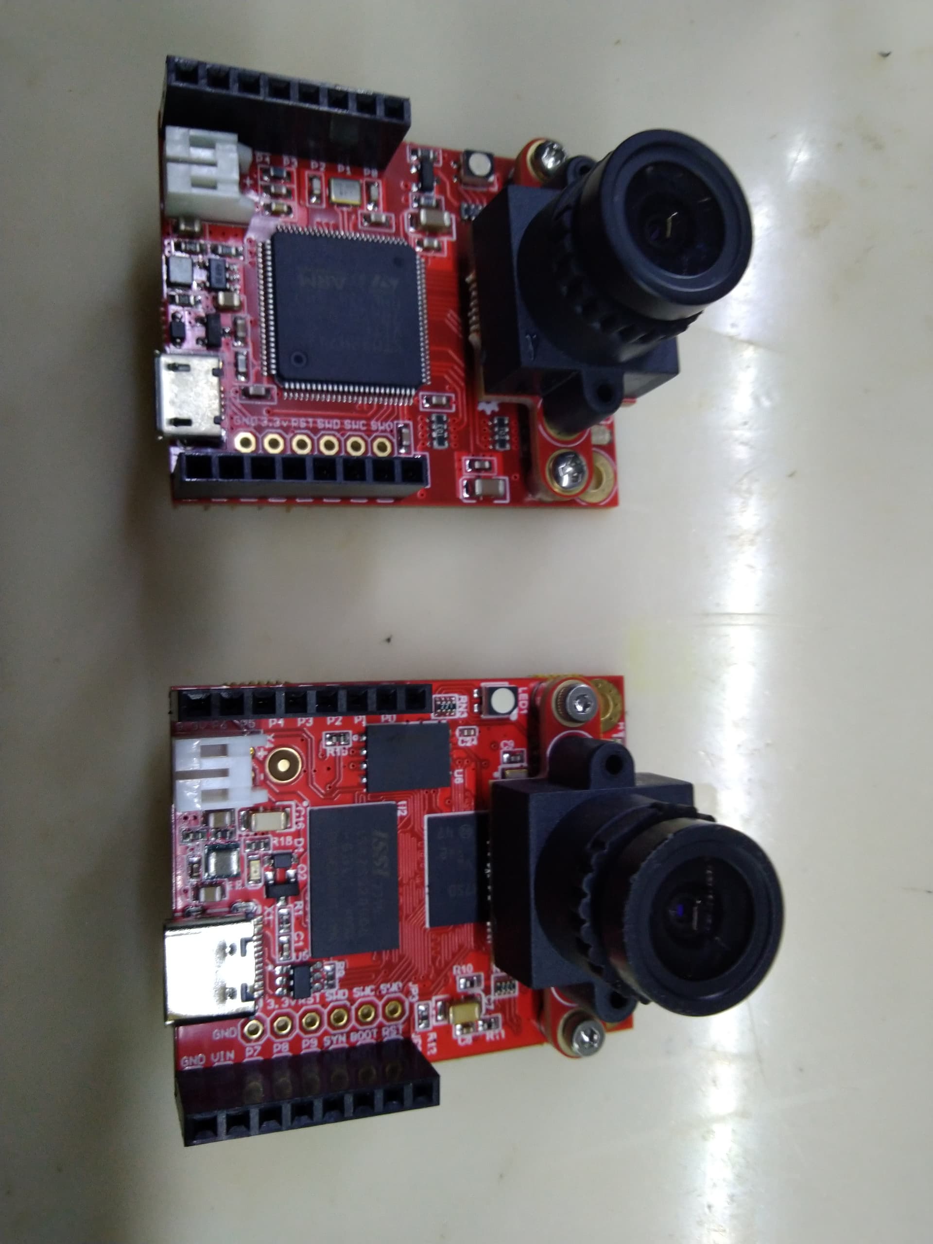
there are all the models
is there some example to follow about YOLOv5?
I tryed it but I have some interpretation problem regarding the model outputs
they seams to not correspond to documentation

m: { model_size: 1975512, model_addr: 0x9180fdf0, ram_size: 676160, ram_addr: 0xc0017780, input_shape: ((1, 224, 224, 3),), input_scale: (0.00392157,), input_zero_point: (0,), input_dtype: (‘B’,), output_shape: ((1, 3087, 6),), output_scale: (0.00770494,), output_zero_point: (3,), output_dtype: (‘B’,) }
i: [<Normalization object at 3000ad90>]
o: [array([[[0.0308197, 0.0308197, 0.0154099, 0.0693444, 0.0, 0.993937],
[0.0308197, 0.0308197, 0.0385247, 0.0616395, 0.0, 0.993937],
[0.0308197, 0.0308197, 0.0462296, 0.0693444, 0.0, 0.993937],
[0.0616395, 0.0308197, 0.0154099, 0.0693444, 0.0, 0.993937],
[0.0616395, 0.0231148, 0.0385247, 0.0462296, 0.0, 0.993937],
[0.0616395, 0.0231148, 0.0462296, 0.0539346, 0.0, 0.993937],
[0.0770494, 0.0231148, 0.0154099, 0.0616395, 0.0, 0.993937],
[0.0770494, 0.0231148, 0.0385247, 0.0385247, 0.0, 0.993937],
[0.0770494, 0.0231148, 0.0462296, 0.0462296, 0.0, 0.993937],
[0.130984, 0.0154099, 0.0154099, 0.0616395, 0.0, 0.993937],
[0.123279, 0.0154099, 0.0385247, 0.0308197, 0.0, 0.993937],
[0.130984, 0.0154099, 0.0462296, 0.0462296, 0.0, 0.993937],
[0.169509, 0.0154099, 0.0154099, 0.0616395, 0.0, 0.993937],
[0.169509, 0.0154099, 0.0385247, 0.0231148, 0.0, 0.993937],
[0.169509, 0.0154099, 0.0462296, 0.0308197, 0.0, 0.993937],
[0.192623, 0.0231148, 0.0154099, 0.0616395, 0.0, 0.993937],
[0.192623, 0.0154099, 0.0385247, 0.0231148, 0.0, 0.993937],
[0.192623, 0.0154099, 0.0462296, 0.0308197, 0.0, 0.993937],
[0.238853, 0.0154099, 0.0154099, 0.0616395, 0.0, 0.993937],
[0.238853, 0.0154099, 0.0385247, 0.0231148, 0.0, 0.993937],
[0.238853, 0.0154099, 0.0462296, 0.0308197, 0.0, 0.993937],
[0.269673, 0.0154099, 0.0154099, 0.0616395, 0.0, 0.993937],
[0.269673, 0.0154099, 0.0385247, 0.0231148, 0.0, 0.993937],
[0.277378, 0.00770494, 0.0462296, 0.0308197, 0.0, 0.993937],
[0.300493, 0.0154099, 0.0154099, 0.0539346, 0.0, 0.993937],
[0.300493, 0.0154099, 0.0308197, 0.0385247, 0.0, 0.993937],
[0.308197, 0.0154099, 0.0385247, 0.0462296, 0.0, 0.993937],
[0.339017, 0.0154099, 0.0154099, 0.0616395, 0.0, 0.993937],
[0.331312, 0.0154099, 0.0385247, 0.0308197, 0.0, 0.993937],
[0.331312, 0.0154099, 0.0462296, 0.0385247, 0.0, 0.993937],
[0.385247, 0.00770494, 0.0154099, 0.0462296, 0.0, 0.993937],
[0.385247, 0.00770494, 0.0385247, 0.0154099, 0.0, 0.993937],
[0.385247, 0.00770494, 0.0385247, 0.0154099, 0.0, 0.993937],
[0.408362, 0.00770494, 0.0154099, 0.0539346, 0.0, 0.993937],
[0.408362, 0.00770494, 0.0385247, 0.0154099, 0.0, 0.993937],
[0.408362, 0.0, 0.0462296, 0.0154099, 0.0, 0.993937],
[0.454591, 0.00770494, 0.0154099, 0.0539346, 0.0, 0.993937],
[0.454591, 0.00770494, 0.0385247, 0.0154099, 0.0, 0.993937],
[0.454591, 0.0, 0.0462296, 0.0154099, 0.0, 0.993937],
[0.493116, 0.00770494, 0.0154099, 0.0462296, 0.0, 0.993937],
[0.500821, 0.00770494, 0.0385247, 0.0154099, 0.0, 0.993937],
[0.500821, 0.00770494, 0.0462296, 0.0231148, 0.0, 0.993937],
[0.516231, 0.0154099, 0.0154099, 0.0385247, 0.0, 0.993937],
[0.516231, 0.0154099, 0.0385247, 0.0231148, 0.0, 0.993937],
[0.516231, 0.0154099, 0.0385247, 0.0231148, 0.0, 0.993937],
[0.531641, 0.0231148, 0.0154099, 0.0616395, 0.0, 0.993937],
[0.531641, 0.0154099, 0.0385247, 0.0385247, 0.0, 0.993937],
[0.531641, 0.0154099, 0.0462296, 0.0462296, 0.0, 0.993937],
[0.57787, 0.0154099, 0.0154099, 0.0616395, 0.0, 0.993937],
[0.585575, 0.0154099, 0.0385247, 0.0231148, 0.0, 0.993937],
[0.585575, 0.0154099, 0.0462296, 0.0308197, 0.0, 0.993937],
[0.6241, 0.00770494, 0.0154099, 0.0539346, 0.0, 0.993937],
[0.6241, 0.00770494, 0.0385247, 0.0154099, 0.0, 0.993937],…

and documentation say:

class yolo_v5_postprocess – YOLO V5

Used to post-process YOLO V5 model output.

Constructors
classml.postprocessing.yolo_v5_postprocess(threshold: float = 0.6, nms_threshold: float = 0.1, nms_sigma: float = 0.1)→ yolo_v5_postprocess

Create a YOLO V5 postprocessor.

threshold The threshold to use for postprocessing.

This post-processor returns a list of rect [x, y, w, h] and score tuples for each class in the model output. E.g. [[((x, y, w, h), score)]]. Note that empty class list are included in the output to ensure the position of each class list in the output matches the position of the class index in the model output.

Best Regards

Giuseppe

.....

Hi,

yolos.zip (2.4 KB)

I’ve attached scripts for YOLOV5/V8/V2. These all work with the H7 Plus, but, speed is very bad.

You can try to use YOLOLC which runs much faster. Change the post-processor to yolo_lc and then find the YOLO LC models in the model zoo under ST. You’ll need to turn off model filtering by board type.

All of this is pre-release, hence the lack of documentation, but, yolo lc will run at 2FPS on the H7 Plus.

Hi
Thanks for scripts !
YOLO_lc is nice.
I have another question
I connected LCD w=240 h=320 and I need to vertically flip LCD
display.SPIDisplay.write
image.png

report a parameter hint=0 (default) and there are a list of flag that can be combined in OR
what is the binary order of this list, es. AREA.0, BILINEAR.1 ecc..? and is it hex or int type
I tryed hex format and HMIRROR bit4 starting from 0 is working : 0x10
but VFLIP do not work:0x20

hint can be a logical OR of the flags:

they are not mapped as documentation suggest
image.png

Regards
Giuseppe

ok I found a way acceptable for me:


import sensor
import time
import display
lcd = display.SPIDisplay(width=240,height=320, bgr=True)

sensor.reset() # Reset and initialize the sensor.
sensor.set_pixformat(sensor.RGB565) # Set pixel format to RGB565 (or GRAYSCALE)
sensor.set_framesize(sensor.QVGA) # Set frame size to QVGA (320x240)
sensor.skip_frames(time=2000) # Wait for settings take effect.
clock = time.clock() # Create a clock object to track the FPS.

while True:
clock.tick() # Update the FPS clock.
img = sensor.snapshot() # Take a picture and return the image.
lcd.write(img,hint=0x40)# hint: >>> HMIRROR=0x10; ROTATE_90=0x40; CENTER=0x80; SCALE_ASPECT_EXPAND=0x800;
#SCALE_ASPECT_IGNORE=0x1000;
print(clock.fps()) # Note: OpenMV Cam runs about half as fast when connected
# to the IDE. The FPS should increase once disconnected.

this code i running on H7 and generate this
H7_rotated_LCD.jpg

but if I run the same code on H7 Plus LCD become dark gray and no image is displayed
What can be the reason?
from documentation the pinout about the P0…P8 is the same
Regards
Giuseppe

(attachments)

Hi, that’s an H7 regular… not an H7 Plus. How is the firmware even running at all onboard?

Regarding the rotation stuff. You have to pass image.ROTATE_180. Notice the module name first.

Yes now Fw Is ok
As told, on H7plus I tested yolo_lc and work.
The picture I sent Is related to H7 with LCD and rotated image
So, to use image.ROTATE_180 I need to import image module, right?

Why the lcd do not work of used with H7 plus and the code i sent?

So, to use image.ROTATE_180 I need to import image module, right?

Yup!

Why the lcd do not work of used with H7 plus and the code i sent?

No idea, it’s the same chip and etc. So, almost all logic is the same. The H7 Plus would have enabled triple buffering with DMA acceleration. You can passing triple_buffer=False to the SPIDisplay constructor.

I know though that the code can drive 320x240 displays fine with DMA accel…

Hi
I tried to use triple_buffer=False but does not solve problem make gray display flipping light intensity
and some pixel row become dirty
respect to triple_buffer=True where disply stay at a fixeed gray scale.

I did a video that render the real behavior

https://drive.google.com/file/d/192Y8eIVYKS2RU_EOOZJ1tgELnAXuGgfS/view?usp=sharing

is it possible that SPI LCD clock has to be adjusted?
have you some more suggest how debug this problem ?

A question About Yolo_lc
the labels file has only the person target, this mean that the loaded model has been trained only on person ?
or it can detect other targets?

Regards
Giuseppe

Could be, the H7/H7P potentially have a different clock freq. 400 MHz versus 480 MHz. Otherwise, they should do indential things.

Do, this, pass the refresh=30 or refresh=15 to the SPILCD constructor. This will lower the clock freq.

As for YOLO_LC, you’ll need to read ST’s notes here: stm32ai-modelzoo/object_detection/st_yolo_lc_v1/README.md at main · STMicroelectronics/stm32ai-modelzoo · GitHub

Hi
I tried your suggest ; only refresh=30 is accepted by interpreter
refresh=15 generate error: invalid refresh rate!
any value below 30 geberate this error.
no chage into lcd behavior.
to exclude a problem with the lcd
I bought a different brand but always ili9341
also this new is working correctly with H7
but do not work with H7Plus
using the code (with necessary pin adjustment) at this link https://github.com/rdagger/micropython-ili9341/tree/master
I tested H7 and both lcd and they work
but H7 Plus no.
my filling is that it is not related to SPI but to framebuffer loading
this code work on H7 but not on H7Plus (the module ili9341.py do not need any change it work out the box)
I use only one raw image due to limited RAM on H7

“”"
““ILI9341 demo (images).””"
from time import sleep
from ili9341 import Display
from pyb import Pin, SPI # type: ignore
import display

backlight=Pin(‘P6’,Pin.OUT)
backlight.value(1)
lcd = display.SPIDisplay(width=240,height=320, bgr=True, refresh=30,triple_buffer=False)

def test():
“”“Test code.”“”

Baud rate of 40000000 seems about the max

spi = SPI(2,SPI.CONTROLLER, baudrate=10000000, prescaler=16, polarity=0, phase=0, bits=8)
settings=spi.class(2)
print(settings)
#spi.init(

display = Display(spi, dc=Pin(‘P8’), cs=Pin(‘P3’), rst=Pin(‘P7’))

if display.width >= 240 and display.height >= 240:
display.draw_image(‘images/RaspberryPiWB128x128.raw’, 0, 0, 128, 128)
sleep(0.1)
“”"
display.draw_image(‘images/MicroPython128x128.raw’, 0, 129, 128, 128)
sleep(2)
display.draw_image(‘images/Tabby128x128.raw’, 112, 0, 128, 128)
sleep(2)
display.draw_image(‘images/Tortie128x128.raw’, 112, 129, 128, 128)
“”"
else:
display.draw_image(‘images/RaspberryPiWB128x128.raw’, 0, 0, 128, 128)
sleep(5)
“”"
display.draw_image(‘images/MicroPython128x128.raw’, 0, 0, 128, 128)
sleep(4)
display.draw_image(‘images/Tabby128x128.raw’, 0, 0, 128, 128)
sleep(4)
display.draw_image(‘images/Tortie128x128.raw’, 0, 0, 128, 128)
“”"
sleep(3)

display.cleanup()
sleep(1)
backlight.value(0)

the two display I am using are these:

(attachments)


Hi, pull the lastest development release from github. See Tools->Install Latest Development release. I just relaxed that requirement down to 1Hz.

Anyway, I literally have an H7 Plus and it works with a 320x240 LCD.

There’s a PR open for a new LCD shield we’ll introduce as a product in the future.

As for your issue. I would suggest scoping the signals for controlling the display and checking if they are all electrically connected. There may be a physical issue.

Hi
you was right , it was a very strange false contact into head strip relative to pin P8
To test both boards H7 and H7Plus, I am using my pyBase 01_Studio
so the same female head strips to alternativly plug both boards for test.
The strange was a false contact on male head pin relative to P8 on H7Plus , the used D/C pin
it has been necessary to deform a little bit the male pin and contact was set true.
now every thing is working at full rate .
Thanks very much !
I tested the last fw release and great now VFLIP is working!!!
I noted that if I use triple_buffer=False , VFLIP doesn’t work any more.
Any way, I tested Yolo_lc with Lcd 2.4" TFT (ili9341), refresh rate=15 and hint= image.VFLIP
result in 1.52 fps w/o IDE connected
attached a photo of test station with lcd showing the person recognition

I am not satisfied about the sensor OV5640 image quality
there is a procedure to calibrate it?
It comes with H7Plus that is a clone.
Furthermore there is a wave phenomena like more dark and more lighted bands that shift on image like a trasparent shade

(attachments)

1 Like

The image should definitely not look that bad. The default quality of our official board is quite good.

If they skimped on the electrical circuits, then the image is going to look terrible.

Given you have a USB-C connector on your board it’s probably a completely different electrical setup.

Hi
Because H7 sensor OV77… Has a good appearance

Can I swap sensor from H7(your official board and sensor) , to H7Plus to see what happen?

Regards
Giuseppe

Yeah, it will just work.

I exechanged the sensor and H7 Plus with OV7725(official sensor of H7) has the same good quality as per H7+OV7725
so H7Pls board seams to have the same electrical features of official one .
So the OV5640 has bad calibration and need some agjustment
I played with sensor adjustment parameter:
sensor.set_auto_exposure(True)

#sensor.set_gainceiling(gainceiling: int)→ None
#Set the camera image gainceiling. 2, 4, 8, 16, 32, 64, or 128
#sensor.set_gainceiling(2)
sensor.set_auto_gain(True, gain_db_ceiling=4)

#sensor.set_contrast(constrast: int)
#Set the camera image contrast. -3 to +3
sensor.set_contrast(-3)

#sensor.set_brightness(brightness: int)
#Set the camera image contrast. -3 to +3
sensor.set_brightness(4)

#sensor.set_saturation(saturation: int)
#Set the camera image contrast. -3 to +3
sensor.set_saturation(-10)

img.gamma_corr(gamma=0.9, contrast=1.1, brightness=0.1)

and all these toghether give an image quality like OV7725
the only problem is this phenomena of light waves that costantly travers the frames

I do not find a parameter that influence it
what can be the reason?

Regards
Giuseppe

(attachments)

That’s the camera sensor exposure; it’s not a multiple of the light frequency. Try manually increasing the sensor exposure and set it to something that’s a multiple of your AC mains frequency.

Hi
before I want o underline that the phenomena has a higher frequency respect to video sent you : , at least 2 or three times.
it is conditioned by code ,was using the SPI and LCD and so the frame rate was 9fps; if I disable LCD fps increase to 46fps

I tested the H7Plus with OV7725 (original sensor) that do not present the problem and I read back the auto_exposure setup
it returns a value 16529 that correspond to 60.499 Hz

Than I tested the H7 with OV5640 and the auto exposure return a value of 23320 that is 42.88Hz

If I tried to start a test in manual exposure and set it to same value 23320 the image becomes very very dark
to get the image with the quality of one obtained with auto exposure i have to increase that value at least to 43320
I tried a multiple of 16529 ; 49587 and also I tried to vary all these values
but at the end they have no effect on problem.

Why the two sensor get an auto exposure complete different to each other?
Why the same exposure time set by auto_exposure do not wor in manual exposure?

But You are right is a frequency generated by lighting
in the room I have two type of led lamps:

  • one is a led strip powered by a dedicated power supply with 12Vdc output
  • the other are led lamps powered directly by AC line 50Hz; normally they have a bridge rectifire and a simple switching supply
    if I turn off these second type of lamps the phenomenon disappears.
    but I am not able to filter it by exposure time on OV5640 sensor.

Regards
Giuseppe