Hello!
I bought this lipo battery that works well with my RT1062 Lithium Ion Polymer Battery with Short Cable - 3.7V 420mAh : ID 4236 : Adafruit Industries, Unique & fun DIY electronics and kits and it charges successfully using this external charger: Adafruit Micro Lipo - USB LiIon/LiPoly charger [v2] : ID 1304 : Adafruit Industries, Unique & fun DIY electronics and kits
According to the product page, if I connect the RT1062 to USB, it should also charge the external battery: “A LiPo battery connector compatible with 3.7V LiPo batteries commonly sold online for hobbyist robotic applications with battery charging support via USB”
However, I have tried this and left it connected for extended periods of time and it never seems to work. Do I need to configure anything in the main.py script in order to charge the battery?
Thanks!
This is all done in hardware. Note that we charge at 100mA rate. I’ve verified that the charger works… it should finish charging. The red light on the right LED on the board will turn on when charging and then turn off when finished.
So, with USB, the green power LED will turn orange when charging and then turn back to green when done.
Thanks Kwabena for the quickly reply!
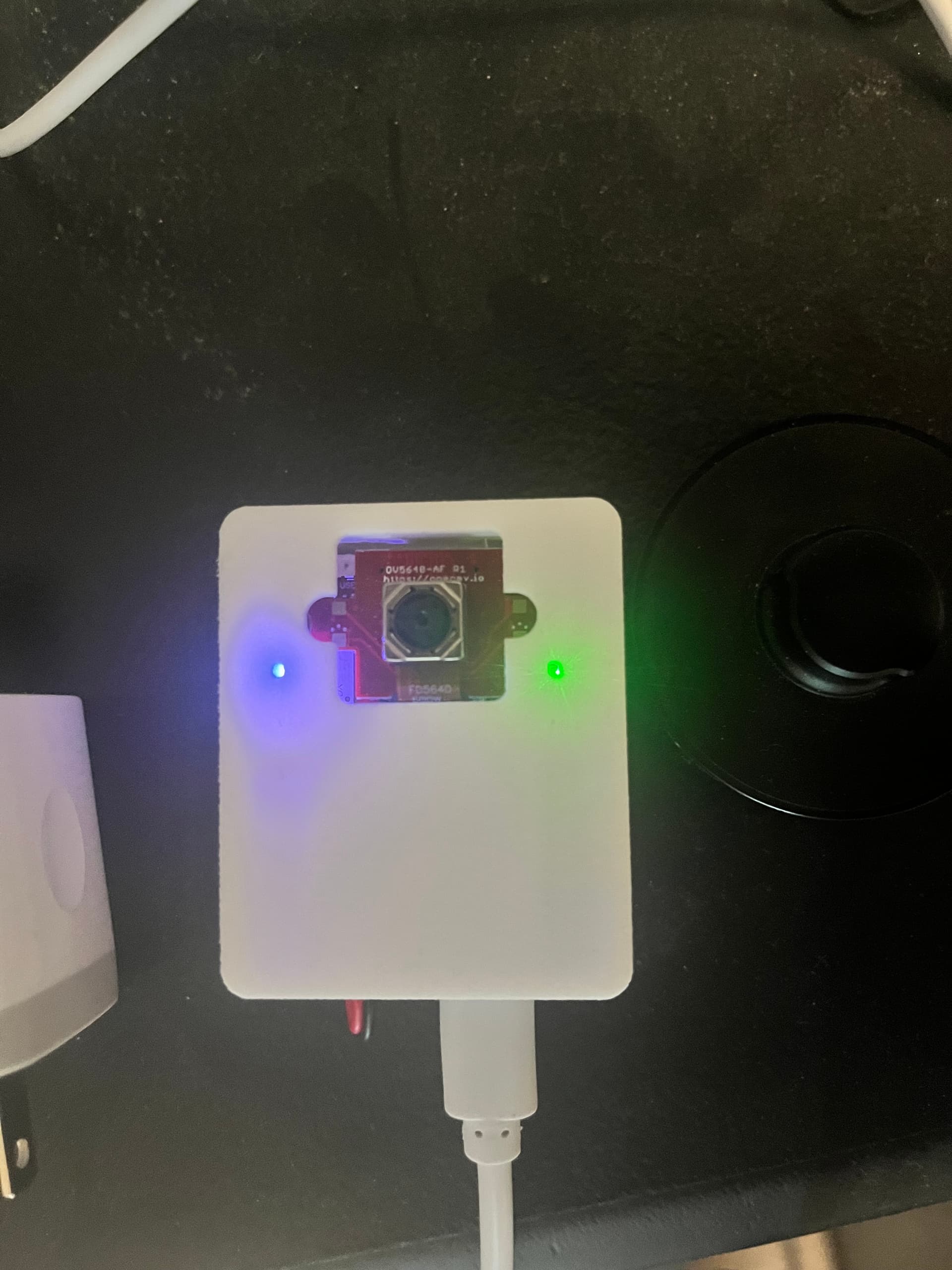
Attached photo for reference once I plug into USB:
Once I plug in the USB the right LED does turn green but it also starts running my main.py script and in it, I put the device into deepsleep after some processing to save battery but it seems doing so also stops the charging process (the LED light goes off).
Does the battery still charge when it is in deep sleep?
The battery will still charge in deep sleep, but, the charging LED is not powered anymore so as to not draw any battery power. So, you won’t be able to tell if it’s charging or not.
The circuit works this way because I designed it to turn the green Power Good LED off when in deep sleep. The charge LED shares the same RGB LED so it turns off too.
It could be possible to make the LED driving logic more complex to power the LED in deepsleep when USB or VIN is available. However, when in deep sleep the LED is not powered. So, it will not be on as of right now.
I’ll see if I can improve this circuit in the future and fix this indication issue. I think I can do it by powering the LED all the time and just using one more transistor to switch off PGOOD when in deep sleep.
Thanks Kwabena - we’ve tried it with multiple RT1062 units and we are still not able to successfully charge it via USB connection. To clarify - we are not charging it via USB to a laptop where the IDE is, we are just using a standard USB charger that is plugged into the wall. Are there any specific requirements to enable charging?
Thanks in advance!
Hi, it just runs when there’s power via USB or VIN. It’s a hardware circuit.
As long as there is VIN or VUSB it will charge. The current limit is set to 100mA. Safey timer is 6.25 hours. Temperature sensing is disabled.
Does your charger require that the host connected to it do USB signaling? The processor will not do this in low-power. We do not do any USB battery charging handshakes.
@openmvfan01 - Can you PM me? Let’s jump on a quick video call to debug this. This circuit works. So, something odd must be going on.
Hi there, any updates on the topic?
In my case, charging also does not seem to work: I plugged in a Lithium battery via the JST connector, and connected the board to the computer via USB-C, but there is no charging indication with the LEDs.
Actually, I cannot even power the RT1062 board when I plug in a 3.8V (measured with voltmeter) lithium battery (similar to the above) into the JST PH2 connector, even though I have a working main.py on the SD card… what is going on?
I expected this to just work as I am pretty sure this is how the H7+ boards I was previously using worked (but I don’t have them anymore, so cannot confirm). Is this different now that the RT1062 has battery charging capabilities, should I plug the battery into the VIN and GND pins instead?
Hi Darrask,
Yeah, we debugged the issue and it wasn’t an issue with the RT1062 board. The battery charger 100% works and charges batteries. The only thing that doesn’t happen is that the charge LED doesn’t light when the board is in power down mode.
Note that the charger will only do 100mA for 6.5hr. So, the battery size is limited to under 600mAhr.
As for it not working with 3.8V… that’s also weird, as it definitely runs off a 3.7V LiPo.
Do you have the right battery connector polarity? Please verify that.
Thanks Kwabena. My bad… I can confirm that the RT1062 board is powered by the Li-ion battery (anything else would be surprising). Maybe I mishandled it between the moment I measured the voltage and the moment I plugged it into the board.
Charging is indeed quite slow. I have a 5000 mAh battery connected to it and am monitoring the voltage at the connector pins periodically while the board is in deep sleep with a wake-up every 5 minutes to blink the LED. I will wait to confirm the progress tomorrow.
What is holding back the charging current to 100mA for 6.5 hours; is it to limit heat buildup? How can we initiate a new 6.5 hour charging bout? Any chance the N6 will have stronger charging specs?
The RT1062’s charging current limit is set to 100mA as this level is safe to use for small LiPo batteries. With the 6.5hr safely timer onboard this means the maximum size with the default battery charger circuit is about 600mA.
However, with a simple resistor change you can increase the current limit from 100mA to 1A. For the 5000mA battery, you’re going to want to do this for charging to work correctly. The ISET resistor is here:
And here are the values to use for different charger limits:
So, you want to replace the resistor with a 890 ohm 0402 resistor. After doing so, it will charge the battery at 1A. This will then fully charge the battery in less than 6.5 hours.
The ILIMIT is set to 1.5A on the battery charger input, so, at 1A charging this means there’s 500mA for the OpenMV Cam RT1062 to power itself with. Note that the USB-C current limit is 1.5A generally for any USB-C ports. Very old USB-A ports may have an issue with this level of current, but, anything that’s USB 3.0 rated (has the super speed pins) should be okay.
…
I’d love to be able to make this kind of limit the default… but, it’s extremely dangerous to do so, as if you use a 1A charge current with a 400mA battery, for example, it most likely will be damaged and explode, eventually causing a fire. 100mA by default is safe and won’t cause any fires and then it’s fairly easy to mod the board to increase the limit.
…
Easiest thing to do is to solder a 1k 0402 resistor ontop of the one there.
Thanks a lot Kwabena - I was hoping that it can be adjusted with a resistor change. Let’s see if we can get this to work, either by replacing the resistor or adding one on top, in parallel.
Actually, our 5000 mAh battery was charged overnight from 3.3V to 4.0V. The board ran a deepsleep script with wakeup to blink a battery every 5 minutes and drew power from the laptop over USB-C to charge the battery that was plugged into the JST PH2.0 connector.
Still, if charging stops after 6.5 hours, how could we reset the timer to start a new 6.5 hour charge - simply by re-connecting USB power? In our case, we would use solar power, so power interruptions are frequent.
Also, I saw that with the N6, though it will be the same charging chip, charging will happen at 500 mA instead of 100 mA - a sensible middle ground. Correct?
Still, if charging stops after 6.5 hours, how could we reset the timer to start a new 6.5 hour charge - simply by re-connecting USB power? In our case, we would use solar power, so power interruptions are frequent.
Yeah, the charger timer resets every time power is disconnected and reconnected.
Also, I saw that with the N6, though it will be the same charging chip, charging will happen at 500 mA instead of 100 mA - a sensible middle ground. Correct?
Yes, I plan to increase this to 500mA on the N6. As long as you don’t use a tiny battery, it’s safe.
Hi Kwabena, is the charging time still limited 6.25 hours on the N6, as suggested by the battery charger datasheet?
Yes, but, it has a 500mA battery charger onboard.