Detecting position and rotation of the openMV camera relative to a computer screen

I’m just going to list down my entire workflow thus far, and perhaps you could tell me where I’m going wrong. I apologize in advance for making yall read through this lengthy post, I was hoping to bring everyone up to speed with what I’ve got so far.

Using this projection model, world coordinates are translated to camera coordinates using the extrinsic matrix for translation and rotation (Mext), then the projection matrix projects the point from camera coordinates to film/image coordinates (Mproj), then its scaled to pixel coordinates using an affine transform (Maff).

Image 1
Using this model, the extrinsic model is easy to understand - its just a 4x3 where the upper left 3x3 is the rotation matrix, the last 3 rows of the last column is the translation vector and the bottom right is a 1 (for homogeneous coordinates I presume):
Image 2

The projection matrix is derived from rules of similar triangles as such:

Image 3
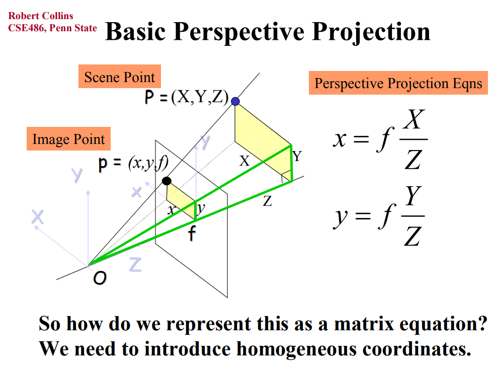
This system of equations can then be rewritten in matrix form using homogenous coordinates (keep in mind the division by Z comes from converting homogenous coordinates back to cartesian):
Image 4

The full matrix then becomes:

Image 5
However as the points lie coplanar on z = 0, the third column of the extrinsic matrix can be eliminated. And since the last row of the projection matrix is 0, the last row of the extrinsic matrix can be eliminated:
Image 6
This then produces a homography matrix, relating the 2 planes together such that (pixel space) = H * (world space):
Image 7
In order to find the values of [h11, …, h13], there are 9 unknowns and each set of correspondence only provides 2 constraints, so with 4 points we only have 8 constraints (shown later). From my understanding, there is 2 ways to set the final constraint; either set h33 to 1, or impose the unit vector constraint on h such that it does not provide the trivial solution of h = 0.
Image 8
However, if h33 is actually 0, the first method does not work, hence the focus shall be on the second method. Multiplying out the homography matrix (expanding matrix multiplication from image 7, last row), we get the set of linear equations:
Image 9
Which can be represented in matrix form as:
Image 10
This can then be solved using SVD (singular value decomposition):
Image 11
Usually in numpy, the column of U (or known as Vt in other literatures) associated with the smallest eigenvalue in D would be the last column (index -1). Reshaping this column of 9 into a (3, 3) matrix then provides the homography matrix.

As we’ve established earlier, the conversion of world points to pixel coordinates involves multiplying the affine matrix, the projection matrix, and the extrinsic matrix. Typically, the intrinsic matrix K is considered to be a combination of the affine and projection matrix (hence the division of pixel size below). The following code is code I’ve written based off my understanding thus far.

def getCameraIntrinsicMatrix(focalLength, pixelSize, cx, cy): #parameters assumed to be passed in SI units (meters, pixels wherever applicable)
    fx = fy = focalLength / pixelSize #focal length in pixels assuming square pixels (fx = fy)
    intrinsicMatrix = np.array([[fx, 0, cx],
                                [0, fy, cy],
                                [0, 0, 1]])
    return intrinsicMatrix

given the focal length (typically mm - convert to m first), pixel size (typically um - convert to m first, and assumed to be square), the center of the image in pixels, the intrinsic matrix is then calculated as shown above.
We need to calculate the homography matrix as well (I’m assuming svd will be implemented in ulab by the time I figure out the rest of this).

def estimateHomography(pixelSpacePoints, worldSpacePoints):
    A = np.zeros((4 * 2, 9))
    for i in range(4): #construct matrix A as per system of linear equations
        X, Y = worldSpacePoints[i][:2] #only take first 2 values in case Z value was provided
        x, y = pixelSpacePoints[i]
        A[2 * i]     = [X, Y, 1, 0, 0, 0, -x * X, -x * Y, -x]
        A[2 * i + 1] = [0, 0, 0, X, Y, 1, -y * X, -y * Y, -y]

    U, S, Vt = np.linalg.svd(A)
    H = Vt[-1, :].reshape(3, 3)

    #verifying u = H*X - comment out if not required
    for pixelPoint, worldPoint in zip(pixelSpacePoints, worldSpacePoints):
        homogeneousWorldCoords = np.array(list(worldPoint) + [1])
        pixelHomogenous = np.matmul(H, homogeneousWorldCoords)
        pixel = list(map(lambda x: round(x), pixelHomogenous / pixelHomogenous[-1]))
        print("H * X =", pixel[:2], " original pixel point:", pixelPoint)

    return H

I’ve verified that multiplying the world points with the homography matrix does indeed return the original pixel values corresponding to that 3D world point.

Now comes the part I’m stuck on - I’ve successfully obtained the homography matrix, I have my camera’s intrinsic matrix, and we’ve established that pixelPoints = H* worldPoints, and H = K * extrinsicMatrix (refer to image 7, middle row) so I assume that by multiplying K^-1 (inverse of K) with H, I should be able to obtain the extrinsic matrix.

def obtainPose(K, H):
    invK = np.linalg.inv(K)
    Hn = invK @ H #normalized by K
    R1 = Hn[:, 0] / np.linalg.norm(Hn[:, 0]) #first column of rotation matrix
    R2 = Hn[:, 1] / np.linalg.norm(Hn[:, 1]) #second column of rotation matrix
    R3 = np.cross(R1, R2) #third column of rotation matrix
    R = np.zeros((3, 3))
    R[:, 0] = R1
    R[:, 1] = R2
    R[:, 2] = R3

    t = Hn[:, -1] #translation vector

    return R, t

The problem is that the translation vector is in the scale of millimeters, when I know for a fact the camera was placed at least tens of centimeters away.

If I’ve gone wrong anywhere please let me know, and if there is a loss of scale somewhere, I’m not sure where it is. Perhaps is it due to homogenous coordinates not being affected by scale due to division of the last element.

Hi, what you posted so far basically sums up what is happening. Please read the code on the post here:

The C code in those posts is literally doing what you just wrote the giant forum post about.

There are comments in that C code which show how the matrices it expects need to be input. Which match what you have researched so far.

The last part which extracts the translation/rotation is what I posted.

Oh my bad, I haven’t went through the links you provided yet… Well if it works for april tags I should definitely examine them in detail. But glad to know my theory matches up so far

I’ve taken a glimpse through the code, and I noticed there’s a matd_svd() function in C. How would I be able to access this in micropython as an end user? As for the matrix math for the rest of the parts, do I have to port it to micropython myself or has it already been done? Ideally I’d like to just “from ulab import numpy as np” and then just call np.linalg.svd(), but given that the code is in C and as an end user I can only access micropython, I’m not sure if I can just include libraries and call C functions from micropython. I’m actually not sure if micropython is actually C in disguise, perhaps it is a wrapper written over C?

As mentioned, the ulab folks are implementing the SVD method. So, once they finish you will be able to use it. You need to port the C code to micropython using ulab.

Alternatively, as I’ve mentioned before, since we already have all the functionality in the code base, if you just want to hack the firmware to add the feature you need it’s really not that hard and you can be done with adding support for this in less than 2 hours.

image — machine vision — MicroPython 1.22 documentation (openmv.io)

Does everything you want… but, it operates on an image. If you just hack the firmware here:

openmv/src/omv/imlib/apriltag.c at master · openmv/openmv (github.com)

You could instead have the function return the pose information.

I do not want to add homography support to the SDK right now as I would like to think about how it should be added as it need to be done cleanly in a way that makes sense for long term use.

I see. Is there an estimated ETA on the implementation of SVD?
It seems this rotation correction function does the opposite of what I want where you provide it translations and rotations and it warps the image accordingly, or is my understanding of this function wrong?

Hi, please contact the ulab developers for when SVD will be implemented. If you follow the thread I linked to you can see the discussion. They already wrote the code for it but it needs to be tested.

You need to modify the code I linked to. However, it shows off how to translate 4-points given to the function in C into the homography matrix. It also shows off how the camera matrix works in C.

Alright, thanks! Perhaps I’ll join in on the other discussion thread.

Hi, I think I’ve somewhat implemented a way to resolve the scale of the homography matrix, I simply scale the translation vector by a scale of 1/((|R1|+|R2|)/2) where R1 and R2 are the first 2 columns of the rotation matrix. For the rotation matrix, is R1 normalised, the R2 is normalised, then R3 is the cross of R1and R2, then R2 is the cross of R3 and R1 (ensuring determinant is +1 for a valid rotation matrix).
The problem now is that the values I’m getting are very very jittery and noisy, and I assume most of this noise comes from trying to track the screen (this returns the 2D screen space coordinates to calculate homography). At the moment I’m using the built-in infinite line detection to find the edges of the screen, then calculating their intersections to find the corners, and it does tend to jump around abit but it does a better job at tracking than blob tracking (using min corners) and definitely does a better job than the built in find rectangles (in terms of jittering and jumping around). April tags also don’t work well because of how low I must set the resolution for it to work.
What other methods can you propose for me to track a computer screen? I’m fine with implementing control measures such as ensuring high contrast between the screen and the background, or a slightly lower frame rate.

find_line_segments() is much better. You can just extend the line segments to be infinite.

Also, you should use a filter on the tracked value and average results.

I used finite line segments before as well, but they seem to split one line or side of my screen into multiple smaller lines. I’ve adjusted the merge angle and merge pixels but it still splits them up. I’ve applied lens correction as well to an arbitrary amount that provides me the straightest lines as well. Sometimes the perpendicular lines don’t exactly join up at the corners, so I’d probably have to extend them to infinity to determine where they meet mathematically.
What do you mean by filter?

I’d just extended them to be infinite to that you can compute where they cross. But, yes, this is harder.

As for filtering, if there’s jitter you just low pass it. However, this will dull the response time.

I somewhat understand low pass filters in the context of signals and frequencies, but how would one apply it to obtaining pixel coordinates of corners on a frame by frame basis?
Another problem with using finite screen lines is that the resolution is kinda stuck at QQVGA, otherwise it’ll run into “out of fast frame buffer stack memory”, whereas I need more resolution because accuracy matters for this application.

I see. Yeah, then filtering is just the final result. You assume it can’t change too quickly over time. So, if the estimate is jittering around you just average the estimate readings.

I’m not sure where you should do this step. Probably best earlier to prevent error growth. So, on the screen, coordinate edges.

The practical implementation of this for example would be to store the average of the past say 10 iterations of all the 4 corners, and average them on their individual x’s and y’s over time assuming the camera cannot make large movements over time?

Yeah, that should work. The trick is how to determine which samples are part of the same group. That will need to be based on a clustering distance metric.

I’ll look into that, thanks! So I take it using hough infinite lines is the best solution for my use case right now?

I guess. It’s the fastest and least memory-intensive method.

1 Like

Hi, I’ve been meaning to ask, when I set the resolution of the camera to say QVGA for example, does it crop or use the sensor’s pixels in the center, or does it use the top left region of pixels? And is there a built in way to estimate the camera’s intrinsics K, similar to the chessboard method on openCV?

Hi,

We use the center of the camera. If it was the top left then you’d notice nothing being centered.

We do not have camera calibration yet implemented. It’s one of my to do list items for ARM this year however.